
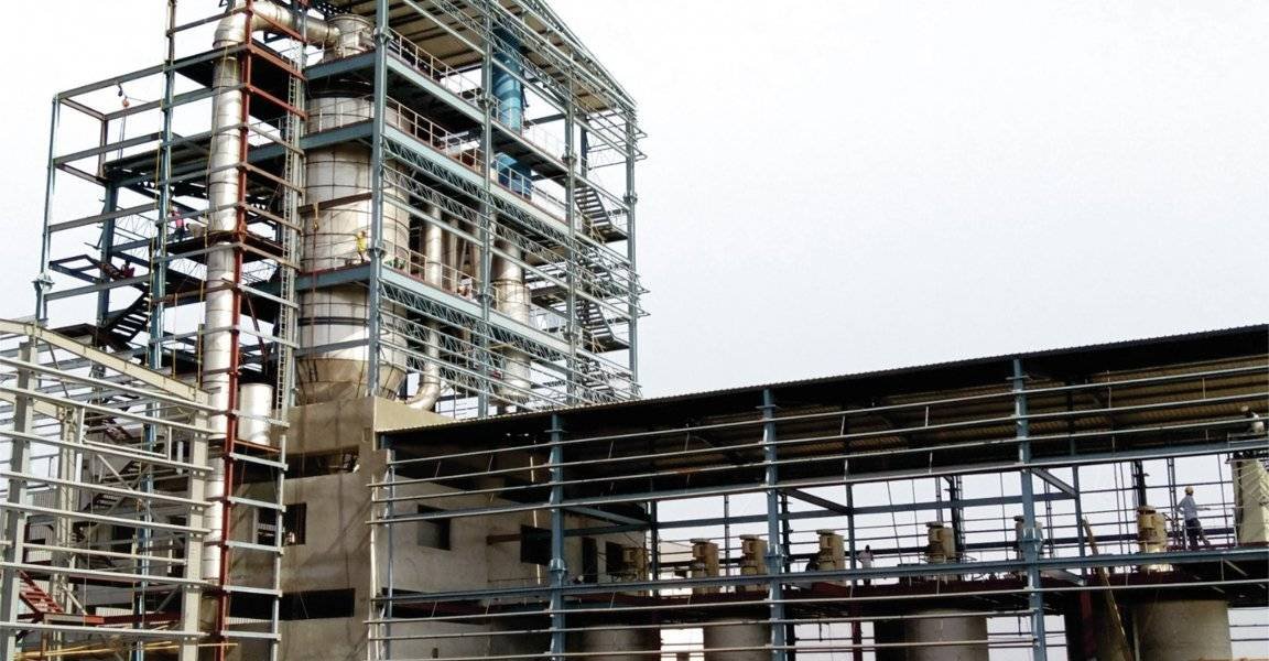

A spray dryer can look complicated the first time you see one in a plant: a tall stainless steel chamber, ducts running in several directions, cyclones, filters, fans and a control panel. A good spray dryer diagram makes sense of all of this. It shows what each part does, how the air and product travel through the system, and where the key measurements and controls sit.
In this guide, Aksh Engineering Systems Pvt. Ltd. explains how to read a spray dryer diagram step by step. We break the system into four simple circuits, label each major component, compare the most common diagram types and share tips that help engineers, buyers and students use diagrams more effectively.
If you are new to spray drying, you may want to start with our article on the spray dryer working principle, then come back here to see how that principle is turned into real equipment.
Why a Spray Dryer Diagram Matters
A diagram is much more than a drawing for a brochure. Different people use it for different purposes:
- Plant owners and buyers use it to understand what they are buying and compare proposals from different suppliers.
- Process engineers use it to check flow directions, temperatures, pressures and equipment sizes.
- Operators use it to understand start-up and shutdown sequences and to locate valves, sensors and alarms.
- Maintenance teams use it to plan access, cleaning and spare parts.
- Students and trainees use it to learn how a spray drying system is organised.
Diagrams come in different levels of detail. A block diagram shows the main stages in boxes. A process flow diagram (PFD) shows the major equipment and the main flows with typical temperatures and flow rates. A piping and instrumentation diagram (P&ID) adds every pipe, valve, instrument and control loop. In this article we focus mainly on the process flow level, which is the most useful for understanding how the system works. For a broader introduction to the machine itself, see what is an industrial spray dryer: working principle, components and flow diagram.
The Simple Way to Read a Spray Dryer Diagram: Four Circuits
The easiest way to read any spray dryer diagram is to follow four separate paths, or circuits, one at a time:
- The air circuit: where the drying air comes from and how it is heated.
- The feed circuit: how the liquid reaches the atomizer.
- The product circuit: how powder is formed, collected and discharged.
- The exhaust circuit: how the used air is cleaned and released.
Here is a simplified flow you can picture while reading:
Ambient air → Air filter → Supply fan → Air heater → Hot air disperser
                                                         ↓
Feed tank → Feed pump → Atomizer ──────────────→ DRYING CHAMBER
                                                         ↓
                              Coarse powder ← Chamber cone discharge
                                                         ↓
                    Exhaust air + fines → Cyclone → Bag filter / Scrubber → Exhaust fan → Stack
                                              ↓            ↓
                                        Fine powder   Fine powder
Let us go through each circuit in turn.
Circuit 1: The Air Circuit
On most diagrams, the air circuit begins on the left or at the top of the drawing.
Air inlet filter. Ambient air is drawn in through a filter that removes dust and contaminants. For food and pharmaceutical dryers, diagrams often show a multi-stage filter train, sometimes ending in a high-efficiency filter.
Supply fan. A centrifugal fan pushes the air into the heater. On a diagram, it is usually shown as a circle with a spiral casing symbol, often labelled with its air volume.
Air heater. This raises the air to the required inlet temperature. Depending on the plant, the heater may be shown as:
- A steam coil heat exchanger.
- A thermic fluid heat exchanger.
- An indirect oil or gas-fired heater with a separate flue.
- A direct gas burner, where combustion gases mix directly with the drying air.
- An electric heater, common in laboratory and pilot units.
Hot air duct and disperser. The heated air travels to the top of the chamber and enters through an air disperser around the atomizer. The disperser is drawn as a ring or cone around the atomizer and is responsible for creating the right airflow pattern inside the chamber.
Look for an inlet temperature sensor just before the chamber. This is one of the most important measurements on the whole diagram.
Circuit 2: The Feed Circuit
The feed circuit is usually drawn alongside the air circuit, leading to the top of the chamber.
Feed tank. Holds the liquid concentrate. It may include an agitator to keep solids in suspension, and a heating jacket to keep the feed at the right temperature.
Feed filter or strainer. Protects the atomizer from lumps and foreign particles.
Feed pump. For rotary atomizers, a variable-speed positive displacement pump is common. For pressure nozzles, a high-pressure pump (such as a plunger or piston pump) is shown.
Atomizer. The heart of the system, located at the top centre of the chamber on most diagrams. It is drawn either as a rotary disc/wheel unit driven by a motor, or as one or more nozzles. Aksh Engineering supplies both rotary and nozzle systems. If you are comparing nozzle types, see our guide to pressure nozzle vs two-fluid nozzle atomization.
Many diagrams also show a water line connected to the feed system. This is used during start-up (spraying water to stabilise temperatures before switching to product) and during shutdown and cleaning.
Circuit 3: The Product Circuit
This is where liquid becomes powder.
Drying chamber. Usually the largest item on the drawing: a tall cylinder with a cone at the bottom. Inside, the atomized spray mixes with hot air and dries. Diagrams often show the spray as a cone or umbrella shape below the atomizer to indicate the spray pattern.
Some diagrams also show:
- Inspection doors and sight glasses for checking the chamber interior.
- Wall sweepers or air hammers to reduce powder build-up.
- Explosion vent panels on the chamber roof or wall, important for combustible powders.
- Lighting for inspection.
Chamber cone discharge. In many designs, the coarser powder settles in the cone and is removed through a rotary airlock valve at the bottom. In other designs, all the powder is carried out with the air and collected in the cyclone.
Powder conveying. Diagrams often show a pneumatic conveying line, screw conveyor or vibrating sieve that takes powder from the chamber and cyclone to a collection point. In two-stage systems, the powder goes to a fluid bed for final drying and cooling first.
Packing station. At the end of the product circuit, powder is collected into bags, drums or bulk containers.
Many of these supporting items are available as part of our spray dryer accessories range, including rotary valves, conveying systems and sieves.
Circuit 4: The Exhaust and Powder Recovery Circuit
After drying, the air carries moisture and fine powder. The exhaust circuit cleans this air before release.
Cyclone separator. Drawn as a cylinder with a cone below it. The air spins inside, throwing particles to the wall, and the powder drops through a rotary valve at the bottom. Clean air exits from the top through a central pipe.
Bag filter. A rectangular or cylindrical housing with filter bags inside, often shown with a pulse-jet cleaning system. It captures fine particles that escape the cyclone.
Wet scrubber. Shown in some diagrams as a final cleaning stage, spraying liquid into the air stream to capture remaining dust. In some processes, the scrubber liquid is returned to the feed to recover product.
Exhaust fan. Draws air through the entire system and keeps the chamber under slight negative pressure, which prevents powder from leaking out.
Stack. The final outlet to atmosphere.
Look for the outlet temperature sensor in the exhaust duct just after the chamber. Together with the inlet temperature, it is the main control point for the dryer. Aksh Engineering supplies complete pollution control systems for this section, and our article on improving powder recovery in industrial spray dryers explains how to reduce product loss in the exhaust.
Instruments and Controls Shown on a Spray Dryer Diagram
A detailed diagram, especially a P&ID, will show many instruments. The most important are:
| Measurement | Typical location | Why it matters |
|---|---|---|
| Inlet air temperature | Hot air duct before chamber | Controls heater output and drying capacity |
| Outlet air temperature | Exhaust duct after chamber | Main indicator of powder moisture; usually controlled by feed rate |
| Chamber pressure | Chamber roof or wall | Confirms the system is under slight vacuum |
| Differential pressure | Across bag filter | Shows when filter bags need cleaning or replacement |
| Feed flow rate | Feed line to atomizer | Keeps product throughput stable |
| Atomizer speed or nozzle pressure | Atomizer drive or feed line | Controls droplet and particle size |
| Fire/CO detection | Chamber and filter | Early warning for fire or smouldering deposits in combustible products |
On a P&ID, these appear as circles with letter codes such as TT (temperature transmitter), PT (pressure transmitter), FT (flow transmitter) and TIC (temperature indicating controller), with dashed lines showing control signals.
Common Types of Spray Dryer Diagrams
Not all spray dryers look the same on paper. Here are the main variations you will see.
Open-Cycle Spray Dryer Diagram
This is the most common layout. Fresh air is drawn in, used once and released after cleaning. It is shown as a straight-through path from air filter to stack. It suits water-based feeds such as milk, food products, detergents and ceramics.
Closed-Loop Spray Dryer Diagram
In a closed-loop system, the drying gas (usually nitrogen) is recirculated instead of being released. The diagram shows the exhaust passing through a condenser, where the evaporated solvent is condensed and recovered, and then returning to the heater. Look for a nitrogen supply line, oxygen analyser and solvent recovery tank. This design is used for organic solvent feeds and oxygen-sensitive products. Learn more about our closed loop spray dryer.
Semi-Closed or Self-Inertizing Diagram
Used for products with explosion risk where water is the solvent. Part of the exhaust gas is recycled to reduce oxygen content in the drying chamber, while the rest is vented.
Two-Stage Spray Dryer Diagram
This diagram adds a fluid bed dryer or cooler after the chamber, either integrated into the chamber base or as a separate external unit. Powder leaves the chamber slightly moist and is dried and cooled gently in the fluid bed. Fines from the cyclone are often returned to the atomizer zone for agglomeration.
Diagrams by Flow Pattern
You will also see diagrams labelled by flow direction:
- Co-current: Air and spray both enter at the top and flow downward.
- Counter-current: Air enters at the bottom and flows upward against the falling spray.
- Mixed flow: A fountain nozzle sprays upward from the bottom while air enters from the top.
Hygiene and Cleaning Features on the Diagram
In food, dairy and pharmaceutical plants, the diagram usually includes Clean-in-Place (CIP) connections. These are shown as spray balls inside the chamber, ducts and cyclones, connected to a CIP supply and return line. CIP allows the system to be cleaned automatically without dismantling, which saves time and improves hygiene. Aksh Engineering offers automatic cleaning-in-place systems designed to integrate with our spray dryers.
Practical Tips for Using a Spray Dryer Diagram
- Follow one circuit at a time. Trace air, feed, product and exhaust separately before looking at the whole picture.
- Check the flow arrows. They show direction of air and product and help you identify co-current, counter-current or mixed flow designs.
- Find the two key temperatures first. Inlet and outlet temperatures tell you the most about how the dryer operates.
- Look for safety features. Explosion vents, fire detection, suppression systems and inerting lines are critical for combustible or solvent-based products.
- Compare diagrams when evaluating suppliers. Differences in powder recovery, heat recovery, CIP or automation often explain price differences.
- Use the diagram during commissioning and training. A clear, up-to-date diagram helps new operators learn the system faster.
- Keep it updated. Every modification to the plant should be reflected on the diagram.
Get a Spray Drying System Designed for Your Process
At Aksh Engineering Systems Pvt. Ltd., every spray dryer begins with a process flow diagram built around the customer's product, capacity, heating source and site conditions. From that diagram, we develop the detailed P&ID, equipment design and layout, and then manufacture, install and commission the system.
Explore our range of industrial spray dryers, and the wider supporting equipment and accessories category, or contact our team to discuss a system tailored to your process.
Conclusion
A spray dryer diagram is the clearest way to understand how a spray drying system works. By breaking the drawing into four circuits (air, feed, product and exhaust), you can quickly see where the air is heated, where the liquid is atomized, where the powder is collected and how the exhaust is cleaned. Adding instruments, CIP and safety features gives you the full picture of how the plant is controlled and maintained.
Whether you are a buyer comparing proposals, an engineer designing a process or an operator learning a new plant, taking time to read the diagram properly will help you make better decisions and run the system with confidence.