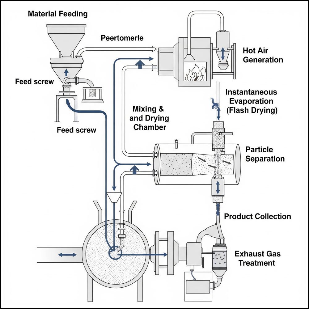
A flash dryer diagram visually represents the key components and the flow of material and gas within a flash drying system. It’s an essential tool for understanding how these industrial dryers operate to rapidly remove moisture from particulate materials.
Here are the typical components and their functions as depicted in a flash dryer diagram:
- Material Feeding System:
- Purpose: To introduce the wet, particulate material into the dryer at a controlled rate.
- Diagram Representation: Often shown as a hopper or bin from which the material is fed, possibly with a screw feeder or rotary valve to ensure consistent input. The material at this stage is typically pre-conditioned (e.g., de-lumped, disintegrated) for optimal drying.
- Hot Air Generation / Heater:
- Purpose: To produce a large volume of hot gas (usually air, but can be inert gas for sensitive materials) that acts as the drying medium.
- Diagram Representation: Depicted as a furnace, burner, or heat exchanger where air is heated to the desired drying temperature. Ducts connect this unit to the mixing chamber.
- Mixing and Drying Chamber (Flash Tube/Duct):
- Purpose: Where the hot gas and wet material are intimately mixed, leading to rapid moisture evaporation.
- Diagram Representation: This is typically a vertical or horizontal duct or tube where the high-velocity hot gas stream entrains and disperses the wet particles. The turbulent flow ensures excellent heat and mass transfer, causing “flash” evaporation of moisture.
- Instantaneous Evaporation (Flash Drying Zone):
- Purpose: The core drying process where moisture rapidly flashes into vapor due to the high temperature and large surface area of the dispersed particles.
- Diagram Representation: This isn’t a separate physical component but rather the event occurring within the mixing and drying chamber. Arrows often indicate the rapid dispersion of particles and release of vapor. The short residence time in this zone is characteristic.
- Particle Separation (Cyclone Separator):
- Purpose: To separate the dried solid product from the spent gas stream.
- Diagram Representation: Typically shown as a cyclone, which uses centrifugal force to separate the heavier dried particles from the lighter gas. The dried product falls to the bottom, while the gas exits from the top.
- Product Collection:
- Purpose: To collect the dried material for further processing, packaging, or storage.
- Diagram Representation: Often depicted as a collection bin, rotary valve, or discharge point at the bottom of the cyclone or after secondary separation stages.
- Exhaust Gas Treatment:
- Purpose: To remove any remaining fine particulate matter from the spent gas before it’s released into the atmosphere, ensuring environmental compliance.
- Diagram Representation: May include bag filters, scrubbers, or electrostatic precipitators located downstream of the cyclone. This section ensures that the emitted gas meets air quality standards.
Flow Representation in the Diagram:
- Material Flow: Usually shown as solid lines or arrows indicating the path of the wet material from feeding through drying and separation to product collection.
- Hot Gas Flow: Typically depicted with dashed lines or arrows showing the path of the hot gas from the heater through the drying chamber and then to separation and exhaust treatment.
- Vapor/Moisture Release: Often indicated by arrows representing moisture evaporating from the material and becoming part of the gas stream.