Evaporators sit at the heart of process industries — from dairy and food processing to pharmaceuticals, chemicals, textiles, and effluent treatment. Whether you’re concentrating milk, recovering caustic soda, or reducing the volume of industrial wastewater in a Multiple Effect Evaporator (MEE) or Agitated Thin Film Dryer (ATFD) system, one question always comes first: how do you correctly calculate evaporator capacity?
Get the capacity calculation wrong, and you end up with an undersized system that can’t meet production targets, or an oversized one that wastes capital and energy. At AKSH Engineering Systems Pvt. Ltd., we design and manufacture evaporation and drying systems for industries across India, and capacity sizing is the single most important step in every project we execute. This guide breaks down the practical engineering approach to evaporator capacity calculation — the formulas, the variables, and the real-world factors that textbooks often skip.
What Is Evaporator Capacity?
Evaporator capacity refers to the quantity of solvent (usually water) that an evaporator can remove from a feed solution per unit time, typically expressed in kilograms per hour (kg/hr) or liters per hour (LPH). It is not the same as the evaporator’s heat transfer area, though the two are closely related through the overall heat transfer coefficient.
In simple terms, capacity answers the question: “If I feed this much dilute solution into the system, how much concentrated product and how much distillate/vapor will I get out, and how fast?”
Capacity calculation matters because it directly determines:
- The size of the calandria or heat exchanger
- The number of effects required (in multiple-effect systems)
- Steam and energy consumption
- Vapor body and condenser sizing
- Overall plant footprint and capital cost
Key Terms Every Engineer Should Know
Before diving into the calculation, it helps to align on terminology:
- Feed (F): The dilute solution entering the evaporator, measured in kg/hr.
- Concentrate/Product (L): The thickened liquid leaving the evaporator.
- Vapor/Distillate (V): The water or solvent evaporated and condensed out.
- Feed Concentration (x_F): Percentage of solids or solute in the feed.
- Product Concentration (x_L): Desired percentage of solids in the concentrate.
- Boiling Point Rise (BPR): The increase in boiling point of the solution compared to pure water at the same pressure, caused by dissolved solids.
- Latent Heat of Vaporization (λ): Energy required to convert 1 kg of liquid into vapor at a given temperature/pressure.
- Overall Heat Transfer Coefficient (U): A measure of how efficiently heat passes from steam to the process fluid, expressed in W/m²·K or kcal/hr·m²·°C.
Step 1: Mass Balance — The Starting Point
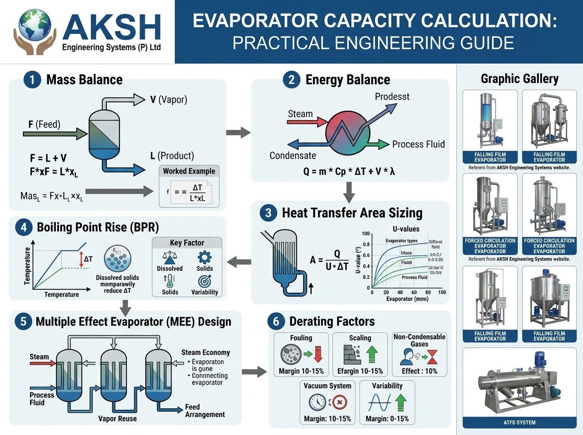
Every evaporator capacity calculation begins with a simple mass balance. The total mass entering must equal the total mass leaving:
F = L + V
And the solute (non-volatile component) balance:
F × x_F = L × x_L
From these two equations, you can calculate the amount of vapor that must be removed:
V = F × (1 − x_F / x_L)
Worked Example
Suppose you need to concentrate 5,000 kg/hr of a feed solution from 8% solids to 40% solids.
- F = 5,000 kg/hr
- x_F = 0.08
- x_L = 0.40
Using the solute balance:
L = F × x_F / x_L = 5,000 × 0.08 / 0.40 = 1,000 kg/hr (concentrate)
V = F − L = 5,000 − 1,000 = 4,000 kg/hr (vapor to be removed)
This tells us the evaporator must remove 4,000 kg of water per hour — this is the foundational number for everything that follows.
Step 2: Energy Balance — Sizing the Heat Duty
Removing water requires energy. The evaporator must supply enough heat to raise the feed to boiling point (sensible heat) and then vaporize the required quantity of water (latent heat).
Q = F × Cp × (T_boiling − T_feed) + V × λ_v
Where:
- Q = Heat duty required (kcal/hr or kW)
- Cp = Specific heat of the feed solution (kcal/kg°C)
- T_boiling = Boiling temperature of the solution at operating pressure
- T_feed = Inlet feed temperature
- λ_v = Latent heat of vaporization of water at the operating pressure
This heat duty (Q) is what your steam supply — live steam, vapor from a previous effect, or thermal fluid — must deliver.
Step 3: Heat Transfer Area — Connecting Capacity to Equipment Size
Once you know the heat duty, the required heat transfer area is calculated using the basic heat transfer equation:
Q = U × A × ΔT
Rearranged for area:
A = Q / (U × ΔT)
Where:
- A = Heat transfer area (m²)
- U = Overall heat transfer coefficient (depends on fluid properties, fouling, and evaporator type — rising film, falling film, forced circulation, etc.)
- ΔT = Temperature difference between the heating medium (steam) and the boiling liquid, corrected for boiling point rise (BPR)
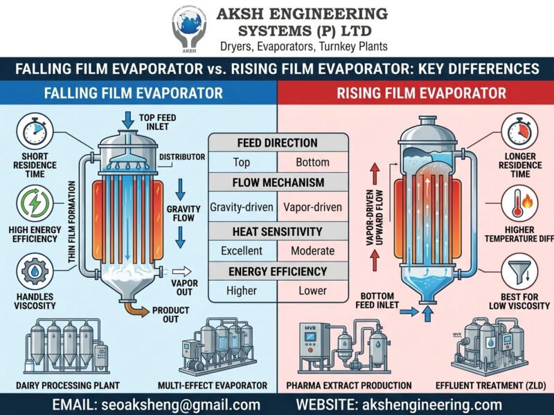
This is where evaporator type matters significantly. Falling Film Evaporators typically offer higher U values and are preferred for heat-sensitive and moderately viscous fluids. Forced Circulation Evaporators are chosen for scaling or crystallizing services, while Agitated Thin Film Evaporators/Dryers handle highly viscous, fouling, or near-solid concentrates at the final stage.
Step 4: Accounting for Boiling Point Rise (BPR)
Many engineers underestimate BPR, leading to undersized equipment. Solutions with high dissolved solids (like caustic soda, salts, or sugar syrups) boil at a temperature higher than pure water at the same pressure. This reduces the effective temperature difference (ΔT) available for heat transfer.
BPR can be estimated using Dühring’s Rule or correlations specific to the solution (e.g., for NaOH, NaCl, or sugar solutions, standard charts and empirical equations are available). Ignoring BPR in the ΔT calculation is one of the most common — and costly — errors in evaporator sizing, since it directly inflates the required heat transfer area if not corrected for.
Step 5: Multiple Effect Evaporator (MEE) Capacity Considerations
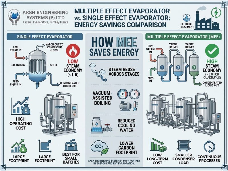
For multiple-effect systems, capacity calculation becomes more layered because vapor generated in one effect becomes the heating medium for the next. Key design principles:
- Steam Economy: In an N-effect evaporator, approximately N kg of water can theoretically be evaporated per kg of live steam supplied (in practice, slightly less due to losses and BPR).
- Equal vs. Unequal Area Design: Effects can be designed with equal heat transfer area (simpler fabrication, common industrial practice) or optimized area distribution (better thermodynamic efficiency).
- Feed Arrangement: Forward feed, backward feed, and parallel feed configurations each affect capacity distribution across effects differently, especially with viscous or temperature-sensitive fluids.
- Pressure and Temperature Drop Allocation: The total available temperature difference (between live steam and final condenser vacuum) is distributed across effects, which governs the area and hence capacity of each individual effect.
For industries like distillery spent wash concentration, dairy, pharma, and Zero Liquid Discharge (ZLD) plants, MEE capacity calculations must also factor in fouling margins, scaling tendencies, and cleaning-in-place (CIP) downtime to ensure the rated capacity is achievable in real operating conditions — not just on paper.
Step 6: Practical Derating Factors Engineers Must Apply
Theoretical calculations give you a starting point, but real-world evaporator performance is always lower than the ideal number unless margins are built in. Experienced process engineers apply derating factors for:
- Fouling and Scaling: Reduces effective U over time; a fouling factor is typically added to the heat transfer coefficient calculation.
- Non-Condensable Gases: Air and CO₂ ingress reduce condenser and heat exchanger efficiency.
- Feed Variability: Seasonal or batch-to-batch variation in feed concentration and flow.
- Vacuum System Performance: Under-sized vacuum pumps or steam ejectors reduce the achievable operating pressure, which in turn affects boiling temperature and capacity.
- Ambient Conditions: ATFD and crystallizer systems in particular are sensitive to cooling water temperature, which affects condenser performance and overall system capacity.
A well-engineered system typically includes a 10–15% capacity margin over the calculated theoretical value to ensure the plant consistently meets production targets under real operating conditions.
Common Mistakes in Evaporator Capacity Calculation
- Ignoring Boiling Point Rise, leading to undersized heat transfer area.
- Using generic U values instead of fluid-specific and evaporator-type-specific coefficients.
- Overlooking fouling and scaling margins, resulting in declining capacity over the plant’s operating life.
- Miscalculating vapor duty in multi-effect systems by not properly accounting for flash vapor and condensate flash recovery.
- Neglecting startup and turndown conditions, sizing only for the nominal operating point.
- Underestimating the vacuum/condenser system’s role in maintaining the design ΔT across all effects.
Why This Calculation Should Never Be Done in Isolation
Evaporator capacity calculation is not just a formula exercise — it’s an integration of thermodynamics, fluid properties, material behavior, and equipment mechanical design. Two evaporators with identical “on-paper” capacity numbers can perform very differently in the field if one properly accounts for fouling, BPR, and vacuum system interaction and the other doesn’t.
This is exactly where experienced evaporator manufacturers add value beyond the formulas. Feed characterization, pilot trials, and application-specific U-value data (built from actual project experience across dairy, chemical, pharma, and effluent treatment sectors) are what separate a reliable, long-life system from one that underperforms within the first year of operation.
How AKSH Engineering Systems Approaches Evaporator Sizing
At AKSH Engineering Systems Pvt. Ltd., every evaporator and drying system we design — whether it’s a Multiple Effect Evaporator, Falling Film Evaporator, Forced Circulation Evaporator, or Agitated Thin Film Dryer (ATFD) — starts with rigorous capacity calculation backed by real process data, not just textbook assumptions.
Our engineering process typically includes:
- Detailed mass and energy balance for the specific feed composition
- Fluid characterization and lab/pilot-scale trials where required
- BPR and fouling-factor-adjusted heat transfer area sizing
- Steam economy optimization for multi-effect configurations
- Application-specific derating for long-term, consistent performance
This approach ensures our clients get evaporation systems sized right the first time — avoiding costly retrofits, capacity shortfalls, or oversized capital expenditure.
Conclusion
Evaporator capacity calculation combines a straightforward mass and energy balance with a series of real-world engineering judgments — boiling point rise, fouling, vacuum system behavior, and multi-effect heat integration — that determine whether a system performs as promised. Getting these calculations right at the design stage is far cheaper than correcting an underperforming plant after commissioning.
If you’re planning a new evaporation system, or need to evaluate the capacity of an existing one, our engineering team at AKSH Engineering Systems Pvt. Ltd. can help with detailed process calculations, feasibility studies, and custom system design tailored to your feed characteristics and production goals.
Get in touch with our team: 🌐 Website: https://akshengineering.com/ 📧 Email: seoaksheng@gmail.com
AKSH Engineering Systems Pvt. Ltd. specializes in the design, manufacturing, and commissioning of Multiple Effect Evaporators, Falling Film Evaporators, Forced Circulation Evaporators, Agitated Thin Film Dryers (ATFD), and Zero Liquid Discharge (ZLD) systems for the dairy, pharmaceutical, chemical, and industrial effluent treatment sectors.