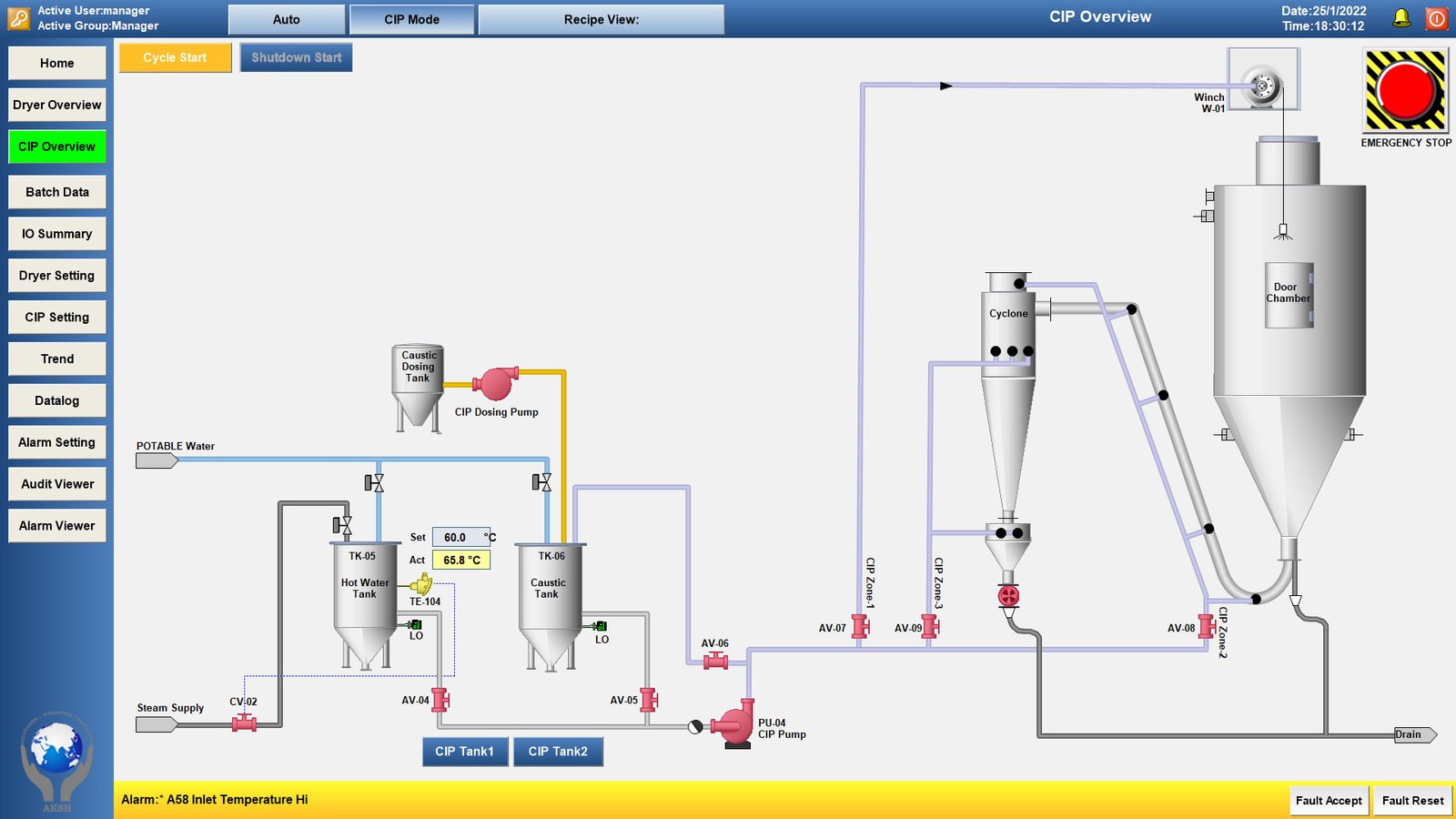
Clean-in-Place (CIP) system, which is an automated method used in industrial settings (like food, beverage, or pharmaceutical production) to clean the interior surfaces of pipes, vessels, process equipment, filters, and fittings, without requiring major disassembly.
Here is an explanation of the key components and the general flow shown in the system:
Chapter 1: Fundamentals of Clean-in-Place (CIP) Technology
1.1 Definition, Historical Context, and Necessity
Clean-in-Place (CIP) is an automated method of cleaning the interior surfaces of pipes, vessels, process equipment, filters, and associated fittings without major disassembly. It is the bedrock of modern hygiene in regulated processing industries. Before the advent of CIP in the 1950s (primarily in the dairy industry), cleaning relied heavily on Clean-Out-of-Place (COP) methods, which involved manual dismantling, scrubbing, and reassembly. This process was inherently time-consuming, inconsistent, costly in labor, and introduced a significant risk of re-contamination during reassembly.
The Imperative for CIP
The necessity of CIP is driven by three core pillars:
- Product Safety and Quality (Non-negotiable): In industries like food, beverage, and pharmaceuticals, residual soils can harbor microorganisms, leading to spoilage, cross-contamination between product batches, and serious health risks. CIP guarantees a reproducible and validated level of cleanliness that manual methods cannot match.
- Operational Efficiency (OEE): Automated cleaning minimizes the downtime required for sanitation. While a COP cycle could take hours, an automated CIP cycle is typically completed in 60-90 minutes, maximizing equipment utilization.
- Regulatory Compliance: Regulatory bodies such as the FDA (Food and Drug Administration) and EMA (European Medicines Agency) mandate strict hygiene standards, particularly in pharmaceutical production (Current Good Manufacturing Practices – cGMP). CIP systems must be validated and documented (using the Audit Viewer and Datalog features shown) to prove that the cleaning process achieves the required sterility assurance level.
The system depicted in the diagram is a Recirculation CIP System, where the cleaning solutions are collected and re-used for multiple cycles, offering significant savings in water and chemical costs compared to a single-use system.
1.2 The Sinner’s Circle: The Science of Cleaning
Effective cleaning, whether manual or automated, adheres to the principles of the Sinner’s Circle. This model visualizes the four critical variables that must be balanced to achieve optimal cleaning performance. In the CIP context, the automated system (PLC and HMI) controls the precise balance of these four factors: Chemistry, Temperature, Time, and Mechanical Action (Flow).
A. Chemistry (The Role of Caustic – TK-06)
The primary chemical shown in the diagram is caustic, typically Sodium Hydroxide, stored in TK-06 (Caustic Tank) and dosed via the Caustic Dosing Pump.
- Function: Caustic is a strong alkali used to break down organic soils, which include fats (lipids) and proteins.
- Saponification: It reacts with fats through saponification, transforming them into soluble soaps that can be rinsed away.
- Hydrolysis: It breaks down complex protein structures via alkaline hydrolysis into smaller, soluble peptides.
- Concentration Control: The precise amount added by the Caustic Dosing Pump is critical. Too little, and soils won’t be removed; too much, and chemical costs rise, rinse times increase, and corrosion risk to equipment intensifies. In modern systems, conductivity sensors (not explicitly labeled but essential) are used to verify the concentration of the chemical in the circulating loop.
While the diagram focuses on caustic, a complete cycle often includes an acid wash (e.g., nitric or phosphoric acid) to remove inorganic soils such as mineral scale, hardness deposits, and rust. The system shown may use one of the unlabeled CIP Tanks (1 or 2) for the acid stage or omit it if mineral scaling is not a concern.
B. Temperature (Controlled by TK-05 and TE-104)
Temperature is the most effective way to accelerate cleaning chemistry. The rate of chemical reactions approximately doubles for every 10°C rise (Arrhenius equation).
- Hot Water Tank (TK-05): The system uses Steam Supply (CV-02) to heat the water inside TK-05, monitored by TE-104.
- Optimal Range: Cleaning with caustic is typically most effective between 65°C and 85°C. The diagram shows a set point of 60.0°C, indicating the system is designed to use hot water for both pre-rinsing and heating the caustic solution.
- Energy Balance: The control valve CV-02 modulates the steam flow to maintain the Set Point (SP) temperature. Excess temperature can “bake on” protein soils, making them harder to remove, while low temperatures severely reduce chemical efficacy.
C. Time (Controlled by the PLC)
Time refers to the duration the cleaning solution is in contact with the equipment surfaces. It is the reciprocal factor to the others:
- If Temperature or Chemistry is maximized, Time can be reduced.
- If Mechanical Action is limited (e.g., complex geometries in the dryer/cyclone), Time must be extended to compensate.
- Validation Requirement: The system PLC must precisely enforce the programmed contact time for each phase (e.g., Caustic Wash Time: 20 minutes) as required by the validated cleaning recipe.
D. Mechanical Action / Flow (Controlled by PU-04 and Flow Meter)
This refers to the physical force applied to the soil layer. In CIP, mechanical action is achieved through the turbulent flow of the cleaning solution.
- The CIP Pump (PU-04): This is the heart of mechanical action. It must generate enough force to achieve turbulent flow in the pipes and generate the necessary pressure for the spray devices inside the vessels (Dryer/Chamber, Cyclone).
- Turbulent Flow: In piping, flow must exceed a certain velocity (typically 1.5 to 2. 5m/s) to ensure the Reynolds number (Re) is greater than 4000 (or often >10,000 for effective cleaning). The high velocity shears the soil off the pipe walls.
- Spray Impingement: Inside the vessels, the pump pressure (Head) determines the coverage and impact force of the fluid exiting the spray devices (the CIP Zones). Inadequate pump capacity will leave shadowed or uncleaned areas.
1.3 Tank System Configurations and Operational Modes
The diagram shows a multi-tank, recirculation-capable system. This design is highly sophisticated and offers flexibility:
A. The Hot Water Tank (TK-05)
- Dual Functionality: It serves as a source for the initial pre-rinse and, critically, as the source for makeup water to create the hot caustic solution in CIP Tank 1/2.
- Level Control: It requires high and low-level sensors (LO/HI) to protect the heater (TE-104) from running dry and to prevent overfilling.
- Potable Water Supply: The supply line from POTABLE Water ensures that the initial rinses and final rinses use water that meets hygiene standards.
B. The Caustic Tank (TK-06) and Solution Preparation
- Storage and Concentration: This tank may hold the return caustic solution that has been used but is still strong enough for re-use.
- Makeup: When the conductivity of the circulating solution drops (due to dilution or consumption), the Caustic Dosing Pump adds concentrate to the active CIP tank (1 or 2) to bring the concentration back to the Set Point.
- CIP Tank 1/2 Selection: The choice between CIP Tank 1 and CIP Tank 2 allows for maximum operational flexibility:
- Option 1 (Common): CIP Tank 1 is the Caustic Tank, and CIP Tank 2 is the Acid Tank (or vice-versa). This allows for a complete, sequential cleaning program.
- Option 2: CIP Tank 1 holds the caustic wash solution, and CIP Tank 2 holds the caustic recovery solution. This enables a continuous process: while one tank is being re-heated and chemically adjusted, the other is actively cleaning.
- Option 3: The tanks are used to store different strengths or types of chemicals for different recipes (e.g., one recipe for light soil, one for heavy soil).
C. Flow Control and Zone Isolation
The use of multiple CIP Zones (1, 2, 3) and dedicated automated valves (AV-07, AV-08) is a key feature indicating system versatility:
- Zonal Cleaning: Not all equipment needs to be cleaned simultaneously or for the same duration. The system can be programmed to clean the Dryer/Chamber (likely Zone 2) first, followed by the Cyclone (likely Zone 1 and 3), or run them sequentially. This minimizes the required flow rate from PU-04 and ensures the full required flow velocity is achieved in the smaller areas.
- Valve Manifold: The arrangement of AV-07 and AV-08 constitutes a valve manifold. This complex piping structure ensures that the cleaning solution only enters the equipment that is intended to be cleaned, preventing cross-contamination and flow diversion.
Chapter 2: Detailed Component Analysis of the Diagrammed System Engineering
This chapter focuses on the specific engineering requirements, design specifications, and functional principles of the major components identified in the CIP diagram. This deep analysis moves beyond the operational view into the domain of process engineering and mechanical design.
2.1 Tank Farm Engineering and Heat Transfer System
The tank farm—comprising the Hot Water Tank (TK-05), Caustic Tank (TK-06), and the primary CIP Tanks (CIP Tank 1/2) is the core storage and preparation facility for the entire cleaning process.
2.1.1 Hot Water Tank (TK-05) Design Considerations
The design of TK-05 must satisfy both thermal efficiency and hygienic requirements.
A. Tank Sizing and Inventory Management
- Volume Calculation: The volume of TK-05 must be sufficient to supply the total fluid required for the largest CIP circuit. This is calculated by summing the volumes of:
- The largest vessel (the Dryer/Chamber).The longest pipe run (return and supply lines).A reservoir volume (heel) in the tank itself.A safety margin (typically 20%).
- Level Instrumentation (LO/HI): The Low (LO) and High (HI) level sensors are critical safety and process interlocks:
- LO Interlock: Prevents the main CIP circulation pump (PU-04) from running dry, leading to cavitation and failure. More critically, it prevents the heating element (TE-104) from activating without sufficient fluid immersion, avoiding burnout and potential vessel damage.
- HI Interlock: Shuts off the POTABLE Water inlet to prevent overflow, which could damage electrical components or violate environmental safety rules regarding fluid containment.
B. Heat Transfer System (Steam Supply and Control)
The objective is to efficiently and safely transfer heat into the cleaning medium.
- Steam Control Valve (CV-02): This is a proportional control valve that modulates the flow of motive steam (high-pressure, saturated) into a heat exchanger coil located inside or adjacent to TK-05.
- Hygienic Design of Heat Exchanger: For sanitary applications, stainless steel (typically 316L) heat exchange surfaces are mandatory, often utilizing dimpled jackets or internal tube coils that are designed for easy drainage and cleaning to prevent bacterial build-up.
2.1.2 Caustic Tank (TK-06) and Chemical Dosing
TK-06 is dedicated to highly concentrated chemical storage and management.
- Material Compatibility: Since caustic (high-pH Sodium Hydroxide) is corrosive, TK-06 must be constructed from highly resistant materials, predominantly 316L Stainless Steel. Welding must be high-quality (orbital welding) to eliminate crevices where corrosion or bacterial growth could occur.
- Caustic Dosing Pump: This is a high-precision metering pump (e.g., diaphragm or peristaltic type) designed for low-volume, high-pressure transfer of concentrated chemical.
- Pulse Control: The PLC sends a pulse signal to the dosing pump, controlling the exact volume added to the circulating loop.
- Safety Features: Requires secondary containment (diking) around the tank and pump due to the hazardous nature of the chemical.
2.2 Pumping Technology: The Heart of Mechanical Action (PU-04)
PU-04 (CIP Pump) is the most critical mechanical component, as it provides the Mechanical Action required by the Sinner’s Circle principle. It must be a robust, sanitary centrifugal pump.
2.2.1 Centrifugal Pump Sizing and Hydraulic Principles
The pump must be sized to overcome the total dynamic head (TDH) and deliver the minimum required flow rate simultaneously across all cleaning zones.
2.2.2 Hygienic Pump Design
- Sanitary Seals: PU-04 must use double mechanical seals with a sterile barrier fluid or steam to prevent the cleaning chemical from leaking into the environment and to prevent non-sterile air/water from being drawn into the product zone.
- Drainability: The pump casing must be designed to be completely self-draining to prevent dead legs where cleaning solution or product residue could harbor bacteria.
2.3 Valve Manifold and Automated Flow Control
The valves (AV-04, AV-05, AV-06, AV-07, AV-08) are not simple on/off switches; they form an intelligent valve manifold that executes the complex routing required for different cleaning recipes and zonal isolation.
2.3.1 Valve Types and Actuation
- Valve Selection: For highly regulated industries, mix-proof valves (or double-seat block-and-bleed valves) are often used, particularly where a CIP line must interface with a product line. A mix-proof valve uses two independent seals and a leak chamber to guarantee that fluid on one side (e.g., caustic) cannot contaminate fluid on the other (e.g., potable water).
- Actuation:AV (Automated Valve) implies an actuator—usually pneumatic. A compressed air signal moves the valve plug.
- Fail-Safe Mode: Each valve is typically designed to fail into a safe position (e.g., Fail-Closed or Fail-Open) upon loss of power or air pressure. For the CIP supply valves, Fail-Closed is common to contain hazardous chemicals.
- Seat Lift: Valves in CIP systems often have a seat lift feature that slightly opens the seal during the rinse phase to clean the area directly under the seat plug, which is otherwise a high-risk contamination point.
2.3.2 Zonal Isolation (AV-07, AV-08)
The core function of these valves is to direct the flow from PU-04 into the correct cleaning target, ensuring the full flow velocity is focused on a single zone at a time.
- CIP Zone 1, 2, 3: Each zone represents a distinct cleaning circuit (e.g., Zone 2 for the Dryer Chamber, Zone 1 for the Cyclone inlet).
- Recipe Control: In the CIP recipe programmed into the PLC (see Chapter 3), the sequence would be:
- Phase 1 (Pre-Rinse – Zone 2): AV-07 closed, AV-08 opens. PU-04 runs. Solution cleans Dryer Chamber.
- Phase 2 (Pre-Rinse – Zone 1/3): AV-08 closes, AV-07 opens. PU-04 runs. Solution cleans Cyclone circuits.
This ensures that the required Reynolds Number for turbulent cleaning is maintained across the entire system, preventing “short-circuiting” where the fluid takes the path of least resistance.
2.4 Integration with Process Equipment (Dryer/Chamber & Cyclone)
The equipment being cleaned—the large vessels on the right—dictates the design of the CIP delivery system.
2.4.1 Dryer Chamber and Spray Device Selection
The large volume and complex geometry of a dryer chamber (often incorporating mixers, heating elements, or filtration) necessitate specific cleaning solutions.
- Static Spray Balls: Simple, reliable, and cost-effective. They rely solely on the pump flow and pressure to flood the entire interior surface. They require very high flow rates (Q) to achieve coverage.
- Rotating Spray Heads (Impingement Cleaners): These devices rotate, using turbine or gear drives to direct high-impact jets of fluid onto the tank walls.
- Benefits: They use less fluid and generate higher shear stress (mechanical action) at the point of contact, making them ideal for removing sticky or hardened soil common in drying applications.
- Winch (W-01) Integration: The presence of a Winch (W-01) suggests that the spray device might be a retractable or lowering head. This allows the device to be lowered into the chamber for cleaning and then retracted above the maximum product level during production, ensuring it does not interfere with the process and is kept clean.
2.4.2 Cyclone and Piping Circuit Cleaning
- Cyclone Cleaning: Cyclones separate fine particles from air/gas streams and accumulate heavy soil (powder) on their internal walls. Cleaning requires complete, uniform coverage down the conical section, necessitating careful placement of spray nozzles/heads (CIP Zone 1/3).
- Piping Drainage and Slope: All piping leading to and from the equipment must have a minimum slope (e.g., 1:100 or 1:50) toward the drain to ensure 100% drainage (preventing “dead legs”) after the rinse phase, which is crucial for microbial control.
- Instrumentation Drainability: Any instrument connections (like pressure transmitters or temperature sensors) must be mounted flush with the pipe wall or via specialized sanitary tees to prevent small, stagnant pockets of liquid from forming.
2.5 Monitoring and Safety Components
2.5.1 Temperature Element (TE-104)
- RTD/Thermocouple: TE-104 is typically a Resistance Temperature Detector (RTD) or thermocouple. It provides the most accurate and responsive temperature feedback for the control loop of CV-02.
- Placement: Its sensor tip must be immersed in the hottest, fastest-moving part of the fluid stream (e.g., right next to the heat exchanger output) to provide a representative measurement.
2.5.2 Emergency Stop (Safety Interlock)
This device is not just a button, but part of a robust Safety Integrity Level (SIL) circuit.
- Function: Activates an immediate, pre-programmed shutdown sequence that overrides the PLC. This typically includes:
- De-energizing PU-04.
- Closing all chemical-containing valves (AV-04, AV-05, TK-06 outlet).
- Shutting off the steam supply (CV-02) and other utilities.
- Lockout/Tagout (LOTO): The E-stop often integrates with LOTO procedures, ensuring that maintenance or repair can only be performed after the system is fully de-energized and locked off.
This chapter has provided a detailed engineering assessment of the main mechanical and thermal components shown in the diagram. The following chapter will focus on the electronic control system and the creation of the automated CIP cleaning recipe.
Chapter 3: Automation, Control, and Operational Sequence
This chapter details the intelligence of the system: the automation architecture, the logic of the Human Machine Interface (HMI), and the precise programming required to execute a validated CIP recipe.
3.1 Control System Architecture (PLC and HMI)
The automated CIP system relies on a two-tiered control architecture: the Programmable Logic Controller (PLC) and the Human Machine Interface (HMI).
3.1.1 The Programmable Logic Controller (PLC)
The PLC is the industrial “brain” of the CIP system, responsible for real-time, high-speed execution of the cleaning logic.
- I/O Handling: The PLC receives Input Signals (I) from field devices and sends Output Signals (O) to control the actuators:
- Inputs: TE-104 (Temperature PV), Level sensors (LO/HI), Flow Meter (Implied), Pressure sensors (Implied), Emergency Stop status.
- Outputs: Control signals to AV-04 through AV-08 (Open/Close), start/stop commands for PU-04, and modulation signal for CV-02 (Steam Valve).
- Interlocking and Safety Logic: A critical function is interlocking—preventing unsafe or impossible operations.
- Example Interlock: The PLC will prevent the caustic transfer pump (PU-04) from starting if CIP Tank 1‘s level is below the LO sensor AND the tank outlet valve (AV-04) is not fully open. This preserves pump integrity and prevents accidental chemical spill.
- State Machine Programming: CIP recipes are typically programmed using a sequential function chart (SFC) or a state machine model. This ensures that the system cannot progress from Phase 2 (Caustic Wash) to Phase 3 (Rinse) until all conditions (Time completed, Temperature maintained, Conductivity verified) for Phase 2 are met.
3.1.2 The Human Machine Interface (HMI)
The HMI (the screen interface shown in the diagram) is the window into the process, allowing the operator to supervise and interact with the system.
- Recipe Management: The Recipe View and CIP Setting tabs allow operators or engineers to select, modify (under password control), or create new cleaning programs based on the equipment being cleaned and the level of soil.
- Parameters Stored in a Recipe: Phase time, Target temperature, Chemical concentration (conductivity SP), Target flow rate.
- CIP Overview and Trend: The main CIP Overview screen provides a dynamic graphic of the process flow. The Trend tab is vital for quality control, allowing visualization of critical variables (PVs) over time to ensure they remained within validated limits throughout the cycle.
- Control Functions: Buttons like Auto, Cycle Start, and Shutdown Start initiate PLC-controlled sequences, transferring authority from manual control to automated recipe execution.
3.2 The Automated CIP Recipe Sequence
The CIP Recipe is the logical sequence of steps required to achieve a validated clean. The system logic must account for precise timing, flow verification, and chemical control. A typical Recirculating Caustic Wash Cycle sequence follows these detailed phases:
Phase 1: Pre-Rinse (Removal of Gross Soil)
| Step | Action | Control Target | Interlock Condition |
| 1.1 | Set Valves | AV-04 open (CIP Tank 1 selection), AV-05 open (return), AV-07 closed, AV-08 open (Isolate Zone 2). | CIP Pump (PU-04) OFF. |
| 1.2 | Fill Tank/Start Pump | Fill CIP Tank 1 with Potable Water. Start PU-04. | CIP Tank 1 level > LO. |
| 1.3 | Circulate Rinse | Flow maintained at minimum (verified by flow meter). | Rinse time elapsed (e.g., 5 min). |
| 1.4 | Verify Drain | Conduct a slug-out (a quick, high-velocity burst of fluid) to sweep out remaining debris. Open drain valve. | Outlet Conductivity sensor (implied) indicates high conductivity (product residue) or rinse time elapsed. |
Phase 2: Caustic Wash (Chemical and Thermal Cleaning)
| Step | Action | Control Target | Interlock Condition |
| 2.1 | Heat Solution | Open CV-02 to introduce steam to TK-05 and fill/heat CIP Tank 1. | CIP Tank 1 temperature = $60.0^\circ\text{C}$ (SP). |
| 2.2 | Dose Chemical | Activate Caustic Dosing Pump until CIP Tank 1 solution reaches required conductivity. | Conductivity sensor PV = $C_{SP}$ (e.g., $20\,\text{mS/cm}$). |
| 2.3 | Circulate Wash | Start PU-04 and maintain flow rate. | Wash time elapsed (e.g., 20 min) AND Temperature $\ge T_{SP}$ for the duration. |
| 2.4 | Zone Switch | Close AV-08, Open AV-07. Circulate through CIP Zone 1/3 (Cyclone). | Second wash time elapsed. |
Phase 3: Intermediate Rinse (Recovery and Water Flush)
| Step | Action | Control Target | Interlock Condition |
| 3.1 | Caustic Recovery | Direct return flow to TK-06 (Caustic Tank) for re-use, until conductivity drops below a set recovery threshold | Conductivity sensor |
| 3.2 | Water Flush | Divert flow to drain. Flush line with Potable Water until conductivity indicates water purity. | Conductivity sensor |
Phase 4: Final Rinse and Verification
| Step | Action | Control Target | Interlock Condition |
| 4.1 | Final Drain | Ensure all lines and vessels are fully drained. | Time elapsed (e.g., 2 min) and Drain valve opens. |
| 4.2 | CIP Complete | Log all cycle data. | All phases successfully completed and verified. |
3.3 Critical Process Variables (CPVs) and Control Loops
The success of the CIP cycle hinges on the precise measurement and control of three primary CPVs: Temperature, Concentration (Conductivity), and Flow Rate.
3.3.1 Temperature Control (PID Loop for CV-02)
The temperature is controlled using a Proportional-Integral-Derivative (PID) control loop acting on CV-02.
- Proportional: The output signal is proportional to the error. A large error (cold tank) means a large opening of CV-02 (more steam).
- Integral : Corrects for persistent, small errors (offset) that the P-term cannot eliminate, ensuring the exactly matches the over time.
- Derivative : Reacts to the rate of change of the error, anticipating large changes and dampening oscillations (overshoot/undershoot), which is critical for preventing thermal shock to equipment.
3.3.2 Concentration Control (Conductivity Measurement)
- Principle: The electrical conductivity of a solution is directly proportional to the concentration of dissolved ionic chemicals.
- Sensor Location: The conductivity sensor (implied) is located on the return line before the recovery or drain diversion valve. This placement verifies that the chemical concentration is correct after the solution has passed through the entire cleaning circuit.
- Dual Use: Conductivity is used to verify two critical points:
- Chemical Concentration (Wash Phase): Ensure the caustic is strong enough
- Rinse Verification (Rinse Phase): Ensure all chemical residues have been removed (conductivity is close to that of the Potable Water).
3.3.3 Flow Rate Verification (Turbulence Assurance)
- Instrumentation: A magnetic flow meter (mag meter) is required on the discharge of PU-04 or the main return line.
- Purpose: The PLC uses the flow rate PV to confirm that the velocity required for turbulent flow is maintained in the pipes . If the flow rate drops below the minimum set point, the PLC must alarm and pause the cycle timer, as cleaning efficacy is compromised. This is a non-negotiable step for validation.
This concludes the deep dive into the system’s automation and operational sequences. The next chapter will address the crucial aspects of safety, compliance, and validation.
Chapter 4: Safety, Validation, and Maintenance
For a process system handling hazardous chemicals and high temperatures under regulatory oversight, safety and validation are paramount. This chapter addresses the legal, procedural, and maintenance requirements for the diagrammed system.
4.1 Personnel and Equipment Safety Protocols
The automated nature of the CIP system, while reducing human interaction, introduces specific risks related to chemical handling, thermal hazards, and pressurized systems.
4.1.1 Chemical and Thermal Hazards
- Caustic Exposure: The handling of concentrated from TK-06 and the circulation of hot caustic requires strict protocols.
- Procedures: Lockout procedures must ensure that the Caustic Dosing Pump cannot be started accidentally during maintenance. Personal Protective Equipment (PPE) is mandatory for any manual interaction.
- High-Pressure Steam: The steam supply controlled by CV-02 is a major hazard. The tank TK-05 must be designed and pressure-tested to handle steam pressure, and all steam lines must be insulated to prevent burns. A Pressure Safety Valve (PSV) is mandatory on the steam jacket/coil to prevent over-pressurization.
- Hot Fluid Lines: All circulating lines must be handled with care. Warning signs regarding temperature are necessary, and line breaks should be avoided during cycle operation.
4.1.2 Emergency Shutdown (E-Stop) and Interlocks
The large red EMERGENCY STOP button is the final safeguard. Its implementation must conform to strict industrial safety standards (e.g., ISO 13849).
- SIL (Safety Integrity Level): The E-Stop circuit is part of a Safety Instrumented System (SIS) and must achieve a specific SIL (often SIL 2 or SIL 3). This means the components (the button, safety relay, and associated wiring) have a statistically verifiable low probability of failure on demand (PFD).
- Interlock Failure Modes: The PLC must constantly monitor the status of critical components. If a valve feedback sensor indicates the valve failed to close (AV-04 stuck open, for example), the PLC must stop the cycle, isolate the chemical source, and trigger the alarm (Fault Accept/Fault Reset required).
4.2 Regulatory Compliance and System Validation
Validation is the documented process of proving that the system consistently performs according to its design specifications and achieves the required level of cleanliness.
4.2.1 GMP and Validation Life Cycle
For pharmaceutical and high-end food applications, the CIP system must comply with Good Manufacturing Practices (GMP). The validation life cycle involves three key phases:
- A. Installation Qualification (IQ): Verifies that the system is installed correctly according to design specifications (P&IDs, equipment manuals). Checks include:
- Verification of materials of construction (316L SS for contact parts).
- Calibration of all critical instruments (TE-104, flow meter, conductivity sensor).
- Verification of utility connections (Potable Water, Steam Supply, Air).
- Confirmation of valve actuation (all AV valves open/close correctly).
- B. Operational Qualification (OQ): Verifies that the system operates correctly under expected (and worst-case) conditions, proving the functionality of the automated sequences. Tests include:
- Functionality Testing: Verification of interlocks (e.g., pump won’t run at LO level).
- Worst-Case Scenario Testing: Running the CIP cycle at minimum temperature and minimum concentration to demonstrate the system can still meet acceptance criteria, highlighting system robustness.
- Control Loop Tuning: Verifying that the PID loop for CV-02 controls temperature without significant overshoot or oscillation.
- C. Performance Qualification (PQ) / Cleaning Validation: The final, definitive proof that the CIP process consistently removes specific target soils and reduces microbial load to acceptable limits. Tests include:
- Soil Spiking: Equipment is deliberately soiled with a standard residue (e.g., riboflavin, milk protein).
- Cycle Run: The validated CIP recipe is executed (e.g., three consecutive successful runs).
- Swabbing and Rinsing: Samples are taken from the hardest-to-clean locations (worst-case spots) on the interior surfaces (swabs) and the final rinse water (rinse samples).
- Acceptance Criteria: Residual soil (Total Organic Carbon – TOC) and microbial load (CFU/cm2 – Colony Forming Units) must be below a calculated, toxicologically justified limit.
4.2.2 Data Logging and Audit Trail (Datalog, Audit Viewer)
- Datalog: Automatically records all critical process data (Time, Temperature, Flow, Conductivity, Valve Status) for every CIP cycle. This data is the evidence for compliance. It is stored on a secure server, often compliant with FDA 21 CFR Part 11 (electronic records and signatures).
- Audit Viewer: This feature tracks all operator actions, parameter changes, and recipe modifications. Any change to a critical set point (e.g., changing the SP for TE-104 from 60 C must be logged with a timestamp, the operator ID, and the reason for the change. This provides an indisputable audit trail.
4.3 Alarms and Troubleshooting
The system is constantly monitored for deviations from the validated recipe parameters.
4.3.1 Alarm Classification and Management
Alarms are classified by severity to guide operator response:
- Low Priority (Warning): Example: “TK-05 Temperature approaching High Limit.” Allows the operator to take corrective action without stopping the cycle.
- High Priority (Critical): Example: “ASR Inlet Temperature Hi” (shown in the diagram). ASR (Auto/Steam Return) is likely a line indicating return flow. A high return temperature could indicate a heat exchanger failure or improper valve alignment. Critical alarms stop the cycle and require immediate operator intervention via Fault Accept/Fault Reset.
- Fatal (E-Stop): Immediate and total shutdown of the system.
4.3.2 Troubleshooting Guide
| Symptom | Potential Root Cause | Corrective Action |
| PU-04 runs but no flow detected. | Blockage (filter, valve failure), or Pump Cavitation (NPSH issue). | Check pump seals; verify all upstream valves are fully open; reduce fluid temperature if near boiling point. |
| Caustic concentration too low (Conductivity low). | Caustic Dosing Pump failure, or insufficient concentrate in TK-06. | Check level of TK-06; check dosing pump calibration and function; extend dosing time. |
| “ASR Inlet Temperature Hi” alarm. | CV-02 (Steam Valve) leakage or failure to close, introducing uncontrolled heat. | Check CV-02 actuator and air signal; isolate steam manually; replace valve seal. |
| CIP cycle fails to pass Final Rinse verification. | Rinse water conductivity remains high. | Check rinse water supply line for contamination; check final drain valve for partial blockage; extend rinse time. |
4.4 Maintenance Strategy
To ensure long-term, validated performance, the system requires a scheduled maintenance program.
- Preventive Maintenance (PM): Scheduled replacement of wear parts, based on operating hours or calendar time. Examples:
- Annual replacement of pump mechanical seals (PU-04).
- Biannual overhaul of valve actuators and seat seals (AV series).
- Periodic draining and flushing of steam traps and strainers (Steam Supply).
- Predictive Maintenance (PdM): Using sensor data to anticipate failure. Example: Monitoring pump motor vibration or bearing temperature to predict an impending pump failure before it occurs, allowing maintenance to be scheduled before production is impacted.
- Calibration: All critical instruments (TE-104, conductivity, flow meter) must be calibrated against certified standards (e.g., NIST traceable) on a defined, validated schedule (e.g., every 6 or 12 months).