The Ultimate Guide to Industrial Spray Dryer Plants: Working Principle, Components, and Flow Analysis
In the modern manufacturing landscape, the ability to transform liquid feed into high-quality, free-flowing powder in a single step is a cornerstone of efficiency. This process is known as Spray Drying.
Whether it’s the milk powder in your pantry, the detergent in your laundry, or the advanced ceramic catalysts used in heavy industry, spray drying technology is the silent engine behind them all. At AKSH Engineering Systems Pvt Ltd, we specialize in designing high-performance spray drying solutions that balance thermal efficiency with product integrity.
1. What is an Industrial Spray Dryer Plant?
An Industrial Spray Dryer Plant is a specialized thermal processing system designed to convert liquid solutions, suspensions, or emulsions into dry powder or granules.
Unlike traditional drying methods that might require multiple stages (filtering, grinding, and drying), a spray dryer completes the transition from liquid to solid in a matter of seconds. This rapid evaporation makes it the preferred choice for heat-sensitive materials, as the cooling effect of evaporation protects the product from thermal degradation.
2. The Working Principle: The Science of Rapid Evaporation
The fundamental principle of a spray dryer is the increase of surface area. By breaking down a liquid into millions of individual droplets, the surface area exposed to heat increases exponentially, leading to near-instantaneous moisture removal.
The Four Stages of Spray Drying:
- Atomization: The liquid feed is pumped into an “atomizer” (either a nozzle or a rotary disk). This device breaks the liquid into a fine mist or “cloud” of droplets.
- Spray-Air Contact: These droplets enter a drying chamber where they meet a high-velocity stream of hot air.
- Drying (Evaporation): As the droplets travel through the hot air, moisture evaporates from the surface. This happens in two phases: the constant rate period (moisture moves to the surface as fast as it evaporates) and the falling rate period (the surface becomes dry, forming a shell).
- Separation: The dried powder is separated from the moist air, usually via a cyclone or a bag filter, and collected for packaging.
3. Core Components of a Spray Dryer Plant
A robust system, like those engineered by AKSH Engineering Systems, consists of several integrated modules:
A. Feeding System
Includes feed tanks and high-pressure pumps (often mono pumps or diaphragm pumps) that deliver the liquid to the atomizer at a consistent flow rate.
B. Air Heating System
Depending on the product requirements, air is heated using:
- Indirect Heaters: Steam radiators or gas-fired heat exchangers (ideal for food/pharma where combustion gases shouldn’t touch the product).
- Direct Heaters: Gas or oil burners where combustion air is mixed directly with the process air.
C. The Atomizer (The Heart of the System)
- Rotary Atomizers: Use a high-speed spinning disk to fling liquid outward using centrifugal force. Great for high-viscosity feeds.
- Pressure Nozzles: Use high pressure to force liquid through a small orifice. Ideal for producing coarser, more uniform granules.
D. Drying Chamber
A large stainless steel vessel where the “magic” happens. The shape (tall-form or wide-body) is determined by the required residence time of the particles.
E. Powder Recovery System
- Cyclones: Use centrifugal force to “spin out” the powder from the air.
- Bag Filters: Use fabric sleeves to capture ultra-fine particles that the cyclone might miss.
- Wet Scrubbers: Often used as a final stage to ensure zero dust emission into the environment.
4. Understanding the Flow Diagram
1. Overview of the System
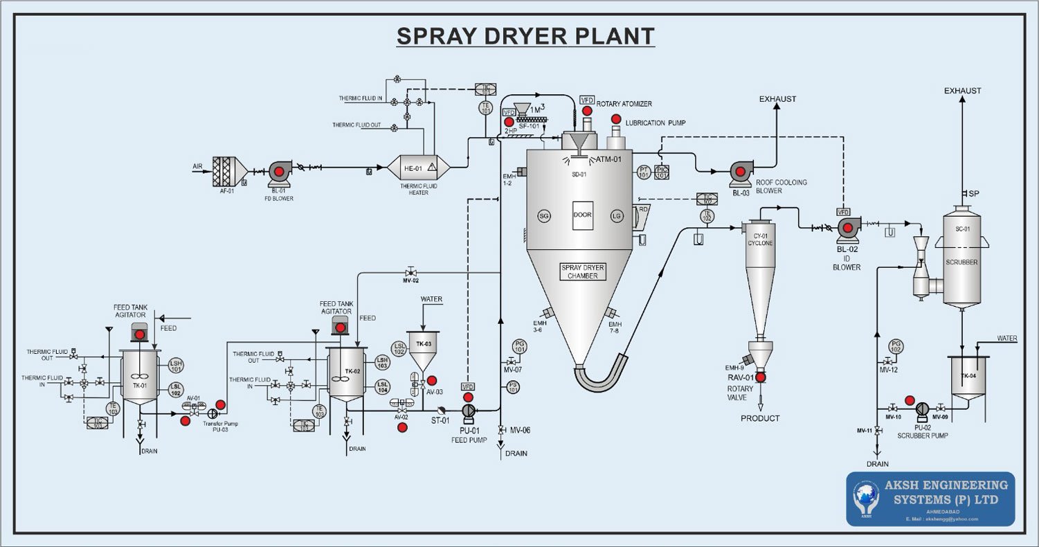
The provided diagram illustrates a sophisticated industrial spray drying plant. The system is designed to take raw liquid feed, process it through heating and atomization stages, and ultimately recover dry product while ensuring environmental compliance through a scrubbing stage.
The plant is divided into four primary sub-systems:
- Feed Preparation and Delivery
- Air Heating and Filtration
- The Drying Chamber and Atomization
- Product Recovery and Exhaust Treatment
2. Detailed Process Flow Analysis
Phase 1: Feed Preparation & Management
The process begins at the bottom left of the diagram with the feed preparation stage:
- Feed Tanks (TK-01 & TK-02): These jacketed tanks are equipped with agitators to ensure the liquid feed remains homogenous. They utilize Thermic Fluid (In/Out) to maintain the feed at a specific temperature, monitored by Temperature Indicator Controllers (TIC-103).
- Transfer & Feed Pumps: The Transfer Pump (PU-03) moves the material between tanks, while the Feed Pump (PU-01), regulated by a Variable Frequency Drive (VFD), precisely delivers the liquid to the top of the drying tower.
- Water Tank (TK-03): This tank provides water for system cleaning or for stabilizing the process during startup/shutdown.
Phase 2: Air Induction and Heating
The drying medium (air) follows a separate path at the top left:
- Air Filter (AF-01) & FD Blower (BL-01): Ambient air is drawn in through a high-efficiency filter and pressurized by the Force Draft (FD) Blower.
- Thermic Fluid Heater (HE-01): The air passes through this heat exchanger, where thermic fluid transfers heat to the air. The temperature is strictly regulated (TIC-101) to ensure the air reaches the precise “Inlet Temperature” required for the specific product.
Phase 3: Atomization and Drying
This is the core of the AKSH Engineering system:
- Rotary Atomizer (ATM-01): Located at the top of the Spray Dryer Chamber (SD-01), this VFD-controlled device spins at high speeds to break the liquid feed into a fine mist of droplets. It includes a dedicated lubrication pump to ensure continuous operation of the high-speed spindle.
- Drying Chamber (SD-01): Inside this large vessel, the hot air meets the atomized mist. Rapid evaporation occurs, turning the liquid droplets into solid powder particles almost instantaneously.
- Monitoring: The chamber features sight glasses (SG), a door for maintenance, and level/pressure sensors (PT/PIC 101) to manage the internal environment.
Phase 4: Product Recovery and Exhaust
The bottom of the drying chamber and the exhaust air stream handle the final product:
- Cyclone (CY-01): The air, now carrying dried powder, enters the cyclone. Centrifugal force separates the heavier powder from the air stream.
- Rotary Valve (RAV-01): The finished PRODUCT is discharged through this valve, which acts as an airlock to maintain chamber pressure while letting the powder out.
- ID Blower (BL-02): The Induced Draft (ID) Blower provides the necessary suction to pull the air through the entire system, from the heaters to the exhaust.
Phase 5: Environmental Protection (The Scrubber)
To ensure no fine dust escapes into the atmosphere, the system includes a final cleaning stage:
- Scrubber (SC-01): The exhaust air enters the scrubber, where water (delivered by Scrubber Pump PU-02 from TK-04) washes out any remaining ultra-fine particles.
- Final Exhaust: The cleaned air is finally released through the stack (SP).
3. Control and Safety Features
The diagram highlights several advanced engineering features implemented by AKSH Engineering Systems:
- Temperature & Pressure Control: Multiple TICs and PICs are distributed across the plant to ensure the process stays within safe and efficient thermal limits.
- Variable Frequency Drives (VFDs): These are used on the Rotary Atomizer and Blowers to allow for fine-tuning of the particle size and airflow, providing versatility for different types of products.
- Roof Cooling Blower (BL-03): This specific blower protects the top of the chamber and the atomizer assembly from overheating, extending the lifespan of the mechanical components.
4. Summary Table of Key Components
| Tag No. | Component | Function |
| SD-01 | Spray Dryer Chamber | The main vessel where evaporation and powder formation occur. |
| ATM-01 | Rotary Atomizer | Uses centrifugal force to create a fine mist from the liquid feed. |
| HE-01 | Thermic Fluid Heater | Raises the process air to the required drying temperature. |
| CY-01 | Cyclone | Separates the dry powder from the air stream. |
| RAV-01 | Rotary Valve | Discharges the finished product without losing system pressure. |
| SC-01 | Scrubber | Cleans the exhaust air to meet environmental emission standards. |
5. Applications Across Industries
| Industry | Common Products |
| Food & Dairy | Milk powder, instant coffee, egg powder, fruit juices. |
| Chemical | Detergents, dyes, pigments, ceramic materials, catalysts. |
| Pharmaceutical | Antibiotics, vitamins, encapsulated flavors, enzymes. |
| Polymers | PVC, resins, stearates. |
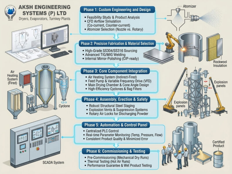
6. Why Choose AKSH Engineering Systems?
At AKSH Engineering Systems Pvt Ltd, we don’t believe in “one size fits all.” Our industrial spray dryer plants are defined by:
- Thermal Efficiency: Optimized heat recovery systems to reduce fuel consumption.
- Precision Control: Advanced PLC-based automation to monitor inlet/outlet temperatures and feed rates.
- Sanitary Design: All contact parts are made of high-grade Stainless Steel (SS304/SS316) with mirror-polish finishes for easy cleaning (CIP).
- Scalability: From pilot-scale R&D units to massive industrial towers producing tons per hour.
Conclusion
An Industrial Spray Dryer Plant is a sophisticated synergy of thermodynamics and fluid mechanics. Understanding the nuances of atomization and airflow is critical to producing a powder that meets your density, moisture, and particle size specifications.